
Use of SOLT calibration kits on the HP/Agilent 8719 (13.5 GHz), 8720 (20 GHz) or 8722 (40 GHz) VNAs.
Much of the development of the short open load thru (SOLT) vector network analyzer calibration kits was performed with the aid of an 8720D, so this analyzer is well known to Kirkby Microwave. We are well used to setting up, configuring and using the 8719/8720/8722 series of instruments to use our VNA calibration and verification kits. Although the 85054 type-N calibration kit can be ordered up to 18 GHz, the model 85033 SMA calibration kit has a maximum frequency of 12 GHz, so does not extend to the full frequency range of the 8719 (13.5 GHz), 8720 (20 GHz), or 8722 (40 GHz) series instruments.
Entering calibration kit definitions into an 8719, 8720 or 8722 series instrument.
Depending on model, three or four of these methods will work.
- Using a floppy disk to enter the calibration kit coefficients. This is the easiest way, but obviously only works on models that
have internal floppy drives.
- Using the Cal Kit Manager 2.1 software to upload the calibration kit coefficients. This software, available from the Keysight website, allows the coefficients to be loaded fairly easily, but there can be some compatibility issues between the software and some GPIB controllers.
- Using the GPIB toolkit written by John Miles, and available from http://www.ke5fx.com/gpib/readme.htm
- Loading via GPIB using other software. This method will be useful if your GPIB controller and the Cal Kit Manager software will not work together.
- From the front panel. This method works on any model in this series and does not require any other software or hardware. However, it is a bit tedious, and easy to make an error.
Method #1 - Using a floppy disk to enter the calibration kit coefficients
Using a floppy disk. If your VNA has an internal floppy disk drive, Kirkby Microwave can supply suitable floppy disks if we are made aware the kit is to be used with an instrument with a floppy disk drive. If you did not request a floppy disk when ordering the kit, or have lost the disk, then let us know the model and serial number of the kit, and we can send a zipfile with the files that need to go on the floppy disk. Just unzip the files to a 1.44 MB 3.5 inch floppy disk. Each calibration kit definitions will have several files with the same prefix, but different suffices. You can use a USB based floppy disk drive. You can put multiple kits on the same floppy disk. Once completed, you should ensure the disk is write protected by moving the little tab so daylight can be seen in the hole.
You should have the following files visible on a disk for the 85033 SMA calibration kit:
- SMA - use this for any single port calibration, or for a 2-port calibration in which there's a flush thru (i.e. one male connector, and one female connector). The delay of the thru is defined to be zero.
- SMA_F_F - use this for any single port calibration, or for a 2-port calibration in which the female-female thru is used. This file includes the delay of the female-female thru, which will be around 41 ps, but is individually measured on each kit.
- SMA_M_M - use this for any single port calibration, or for a 2-port calibration in which the male-male thru is used. This is quite rare, as new people use two female cables. This file includes the delay of the male-male thru, which will be around 75 ps, but is individually measured on each kit.
You should have the following files visible on a disk for the 85054 N calibration kit:
- N - use this for any single port calibration, or for a 2-port calibration in which there's a flush thru
(i.e. one male connector, and one female connector.) The delay of the thru is defined to zero.
- N_F_F - use this for any single port calibration, or for a 2-port calibration in which the
female-female thru is used. This file includes the delay of the female-female thru,
which will be around 80 ps, but is individually measured on each kit.
- N_M_M - use this for any single port calibration, or for a 2-port calibration in which the male-male thru is used. This is quite rare, as few people use two female cables. This file includes the delay of the male-male thru, which will be around 130 ps, but is individually measured on each kit.
Once you have the floppy disk with the correct files, the method is:
- Power on, or press "Preset" if the VNA is already on.
- Insert the floppy disk
- Press the "Save/Recall" key
- Press the softkey for "Select disk"
- Press the softkey "Internal disk"
At this point, assuming your floppy drive still works, you should get a list of the files on the floppy. Pick the one for the kit. The name should be obvious. For example, for our SMA kit, it will be SMA or KM85033. For the N kit it will be KM85054. For other kits, the names should be obvious. You can store multiple kits on the same disk. Each entry has several files, which you can see on a PC, but will not see on a VNA.
- Press the softkey "Return"
- Use the knob to select the calibration kit file.
- Press the softkey "Recall state"
that will then load the coefficients into the USER kit. When the VNA is powered off, assuming the super capacitor (supercap) (early models) or battery (later models) is ok, the contents of the user defined calibration kit will be stored. There should be no need to load them again. Note however that when the instrument is rebooted, either via pressing the PRESET button or by powering it off, the calibration kit will revert to the default for that instrument.
Method #2 - Using the Cal Kit Manager 2.1 software to upload the calibration kit coefficients
The VNA Cal Kit Manager 2.1 software is designed to connect to many VNAs, including the 8753, 8719, 8720 and 8722, using GPIB. It needs a National Instruments, HP or Agilent GPIB controller. There are reports this software does not work with recent National Instruments USB GPIB controllers.
The procedure to use is:
- Obtain a .ckm file for your calibration kit. You can either
- Ask us to create the file, telling as the model and serial number of your kit. We will send it by email.
- Create the .ckm file yourself, using the data on the USB stick and the instructions on our website about creating .ckm files.
- Install the Cal kit Manager 2.1 software.
- Run the software, and open the .ckm file.
- Select your model of VNA on the VNA menu of the software
- Select Send kit to VNA on the software.
Although we have never used it outselves, being Unix fans, and not Windows fans, the
Windows based GPIB toolkit has a number of useful features for test equipment. One is a program
called vna.exe, which can manipulate calibration kit files, as well as save Touchstone files.
Method #4 - Writing your own software to upload the coefficients.
If you look at the programming manual for the VNA, you will see that there are various commands to
set up calibration kits. Below are a list of commands which were used to set up a custom calibration kit
on one particular VNA. The basic procedure is
- Load the default N calibration kit, with CALKN50
- Modify various values.
- Label the calibration kit, with LABK
- Save the calibration date to the USER calibration kit with SAVEUSEK
You should be able to see this happening in the code below, but this is only an example
of the sort of things your own software might do, and some of the command may not be supported
by your instrument anyway. You need to read the programming manual.
CALKN50;
MODI1;
DEFS1;
STDTSHOR;
OFSD 4.1398E-11 ;
OFSZ 5E1 ;
OFSL 2.2E9 ;
MINF 0E0;
MAXF 7E9;
STDD;
DEFS2;
STDTOPEN;
OFSD 3.96E-11 ;
OFSZ 5E1 ;
OFSL 2.2E9 ;
C0 7.1252E1 ;
C1 -1.19 E3;
C2 -1.10417E2 ;
C3 -9.64691E-1 ;
MINF 0E0 ;
MAXF 7E9 ;
STDD;
DEFS7;
STDTSHOR;
OFSD 5.7834E-11 ;
OFSZ 5E1 ;
OFSL 2.2E9 ;
MINF 0E0 ;
MAXF 7E9 ;
STDD;
DEFS8;
STDTOPEN;
OFSD 5.51E-11 ;
OFSZ 5E1 ;
OFSL 2.2E9 ;
C0 5.80514E1 ;
C1 5.80271E3 ;
C2 -2.51433E3 ;
C3 2.01427E3 ;
MINF 0 ;
MAXF 7E9 ;
LABK "SMA";
KITD;
SAVEUSEK;
Method #5 - From the front panel.
If possible, it is much easier to enter a calibration kit via GPIB or a floppy disk, but if you don't have that facility, then
you must define it manually. The manual for the VNA needs to be consulated carefully, but an outline of the procedure is
given below, where on modifies one of the internal kits and saves it as a USER kit. That is much easier than trying to define the kit from scratch. By re-defining a suitable calibration kit, you can avoid having to worry about CLASS ASSIGMNMENTS, and only concern yourself with changing the standard definitions. So an outline of the procedure is as follows. These photographs were taken from an HP 8720D VNA with 7.74 firmware, but an 8753ES with the same firmware versions shows almost identical behaviour. Different VNAs and different firmware versions might change the menu structure a little, but this should indicate the process.
Some standards are easier than others to define, as they have less parameters. In order of complexity, from the simplest to the most complicated, we have
- Loads - these are the easiest to define.
- Shorts
- Opens
Since the opens are the most complicated things to define, this tutorial will define an open standard. The shorts and loads only have a subset of the parameters of the opens.
- Press PRESET on the front panel, to get the VNA into a known state. When the instrument is preset, the default calibration kit for the instrument will be loaded. The default calibration kit for that instrument which might be something like:
- CAL KIT [7 mm] on an 8753 series instrument with APC7 connectors.
- CAL KIT [N 50 Ω] on an 8753 series instrument with N connectors.
- CAL KIT [3.5 mmD] on an 8719 or 8720 series instrument.
- CAL KIT [2.4 mm] on an 8722 series instrument
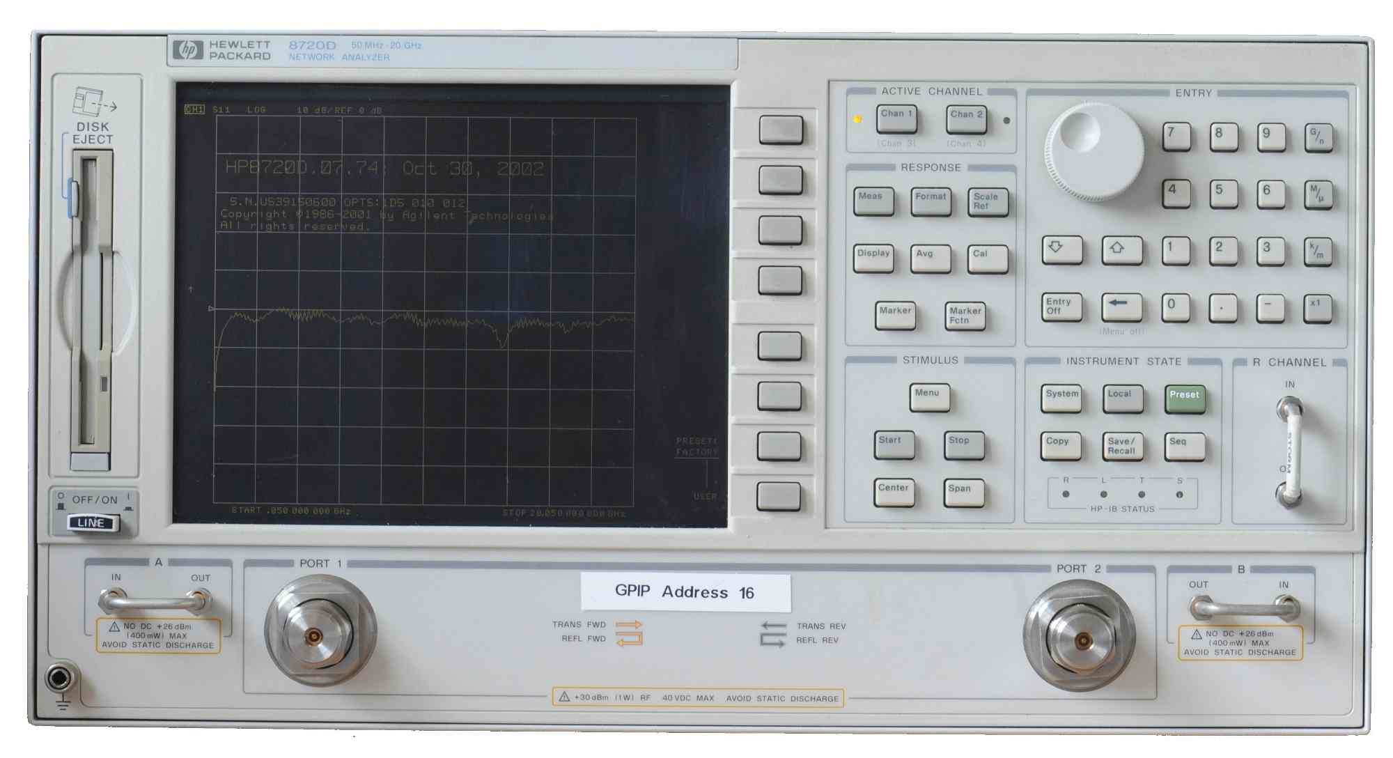
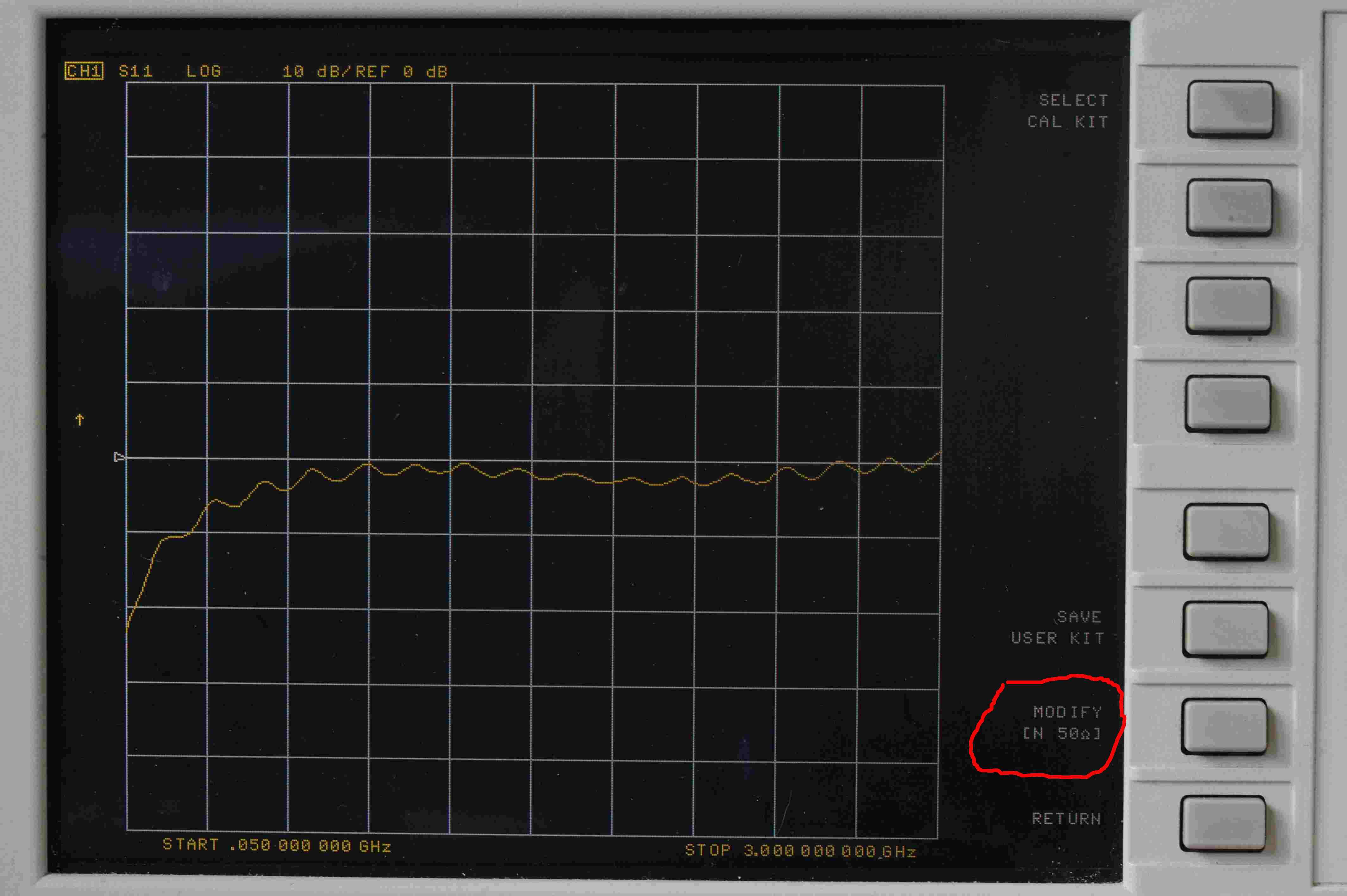
- Press CAL on the front panel. You should see the normal calibration screen. One part of the screen should show the currently loaded calibration kit, which, as stated above, will be the default kit.
- Press the soft key to the right of the 'CAL KIT [xxx]', as we want to change from that default kit to something else.
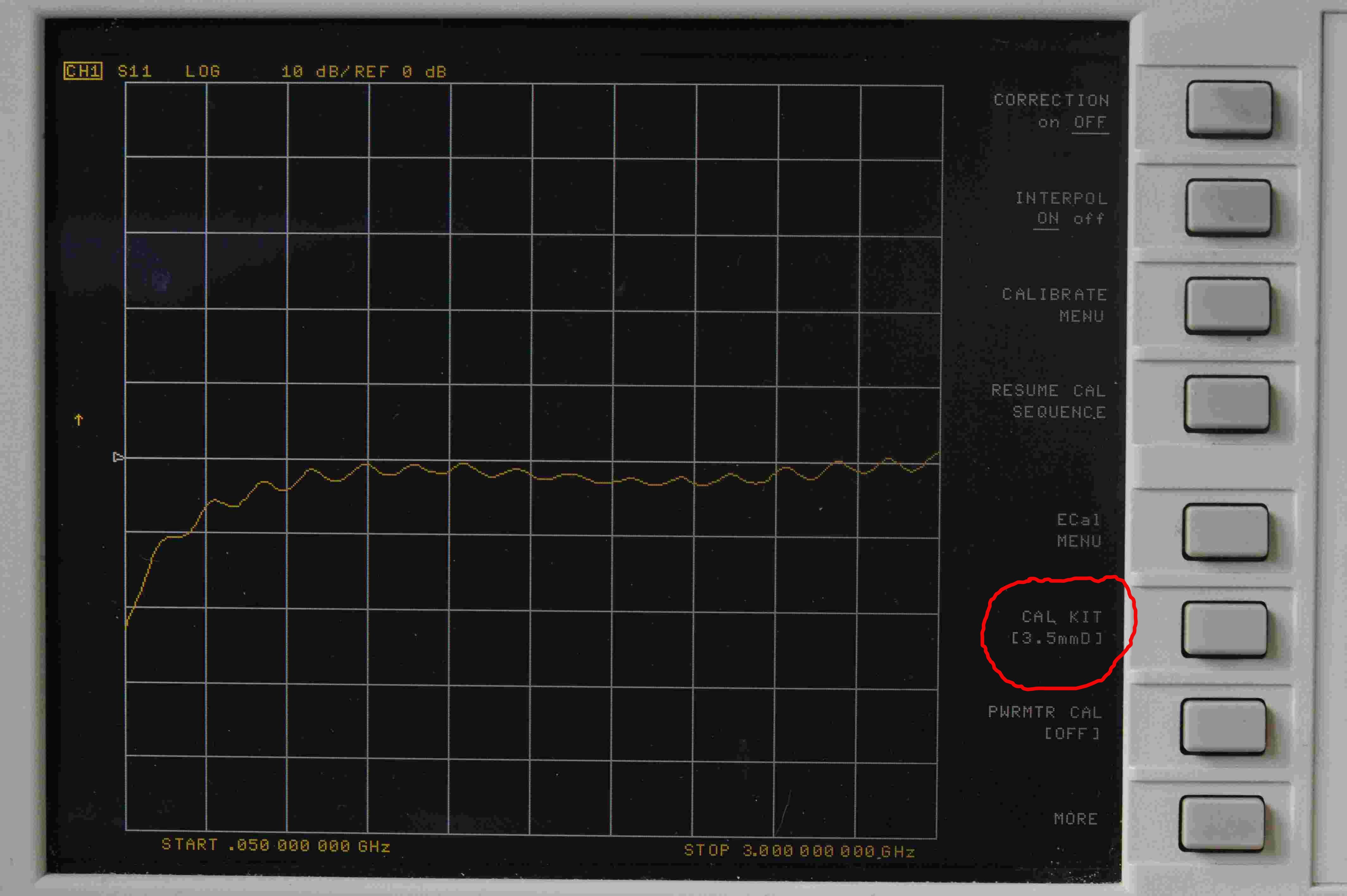
- Press the soft key to the right of 'SELECT CAL KIT', which is circled in red.
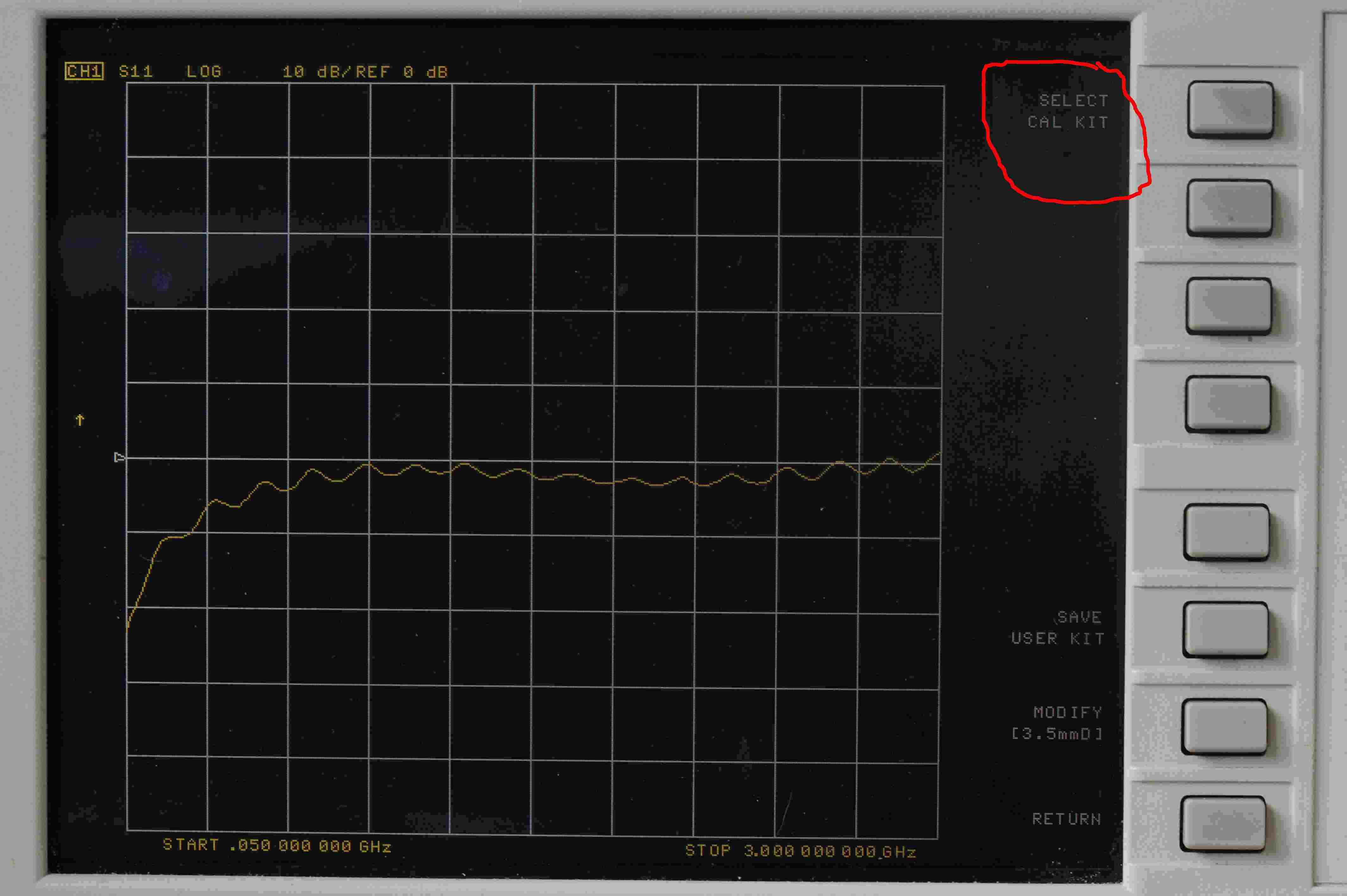
You should now see a list of calibration kits. One, the default kit, in this example an 85052 series kit, will be underlined, as shown. Change the calibration kit to one of either 'N 50 Ω 85032B/E' (on an 8753) or 'N 50 Ω 85054' (on an 8719, 8720 or 8722) - use the N kit, even if using our SMA kit. Do not use the 85032F kit if it is in the firmware. Even though the 85032F is is an N kit, it is not a good choice to modify for our purposes, even
if defining an N calibration kit. The reason for this is the 85032F has the same coefficients for the
male and female standards, whereas most Agilent kits, and all Kirkby Microwave kits, do not have identical
coefficients for the male and female standards.
- Once an N kit is selected, press the soft key for 'RETURN'
- Press the soft key for 'MODIFY [N 50 Ω]'
Which will then show a screen like this
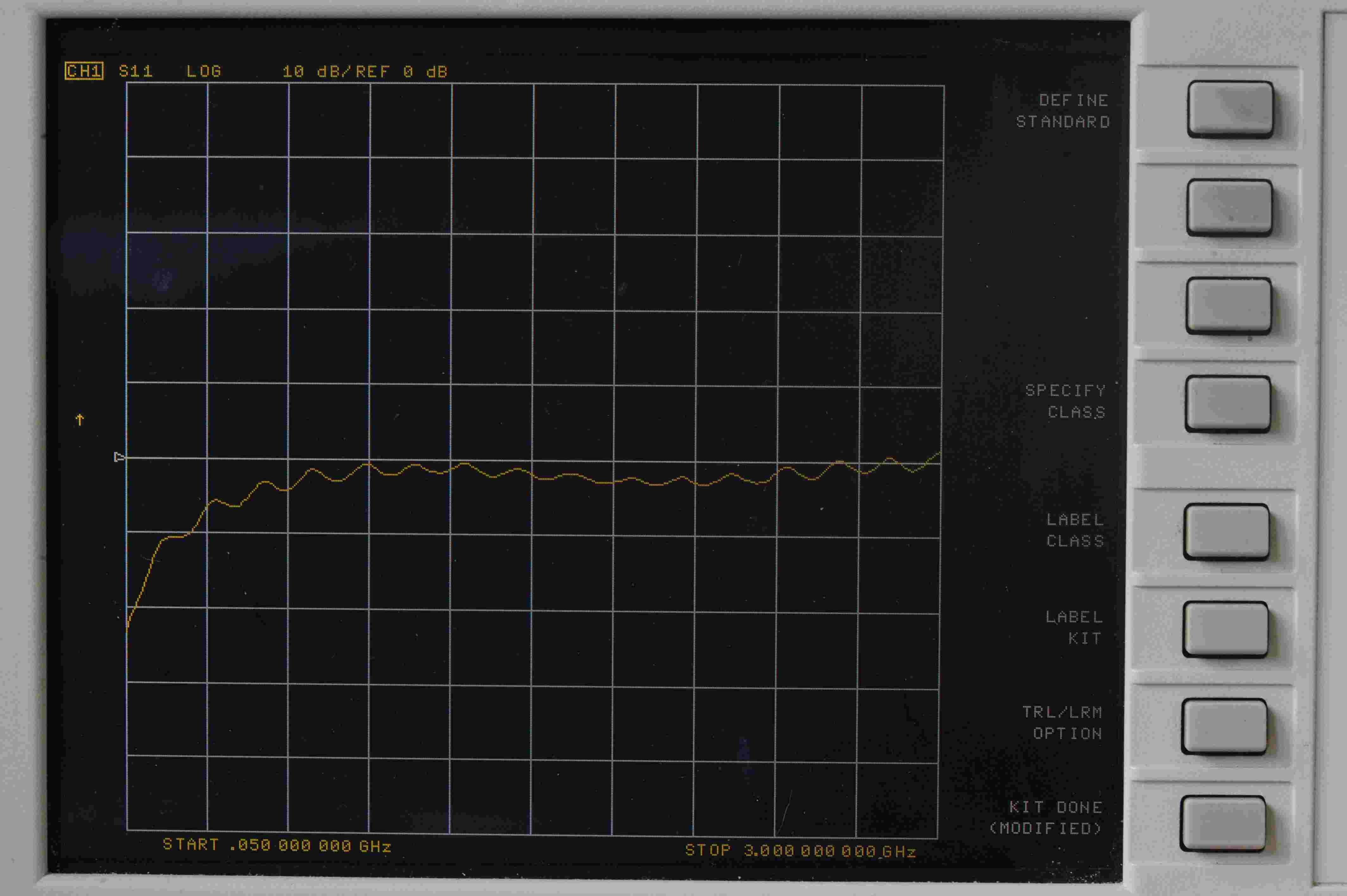
- Press DEFINE STANDARD
and obseve that calibration standard #1 is a short, as SHORT is underlined.
It is important not to alter standard #1 from SHORT to anything else! This is an easy mistake to make. People want to modify
an open standard, so they press the OPEN softkey, which would then define standard #1 to be an open. That would be bad news. The actual standards are as follows, and must remain as follows
- Female SHORT
- Female OPEN
- LOAD
- DELAY/THRU
- LOAD
- LOAD
- Male SHORT
- Male OPEN
It is not apparent from the above picture that the standard #1, which is a SHORT, is a female short, but it is. (If you press MODIFY STD DEFINITION, then LABEL STD, you will see the label is SHORT (M), which is
a female short, because the gender on the HP menus refers to the test port, and not the calibration standard. But we will not do that now, but check if you wish.)
The open standards are more complicated than the shorts to modify, as they have all the same parameters as a short (impedance, offset delay, offset loss), but some additional parameters (C0, C2, C2 and C3) too. So in this tutorial we will modify the parameters of the female open. Once you know how to modify an open standard, modifying the parameters of any other standard, such as a short, load or thru, will be relatively easy.
In order to modify the coefficients of an open standard, do not press OPEN, as that will redefine standard #1 to be an open! That will really mess things up. One should use the rotary controls or up/down
arrows to select a different stanard.
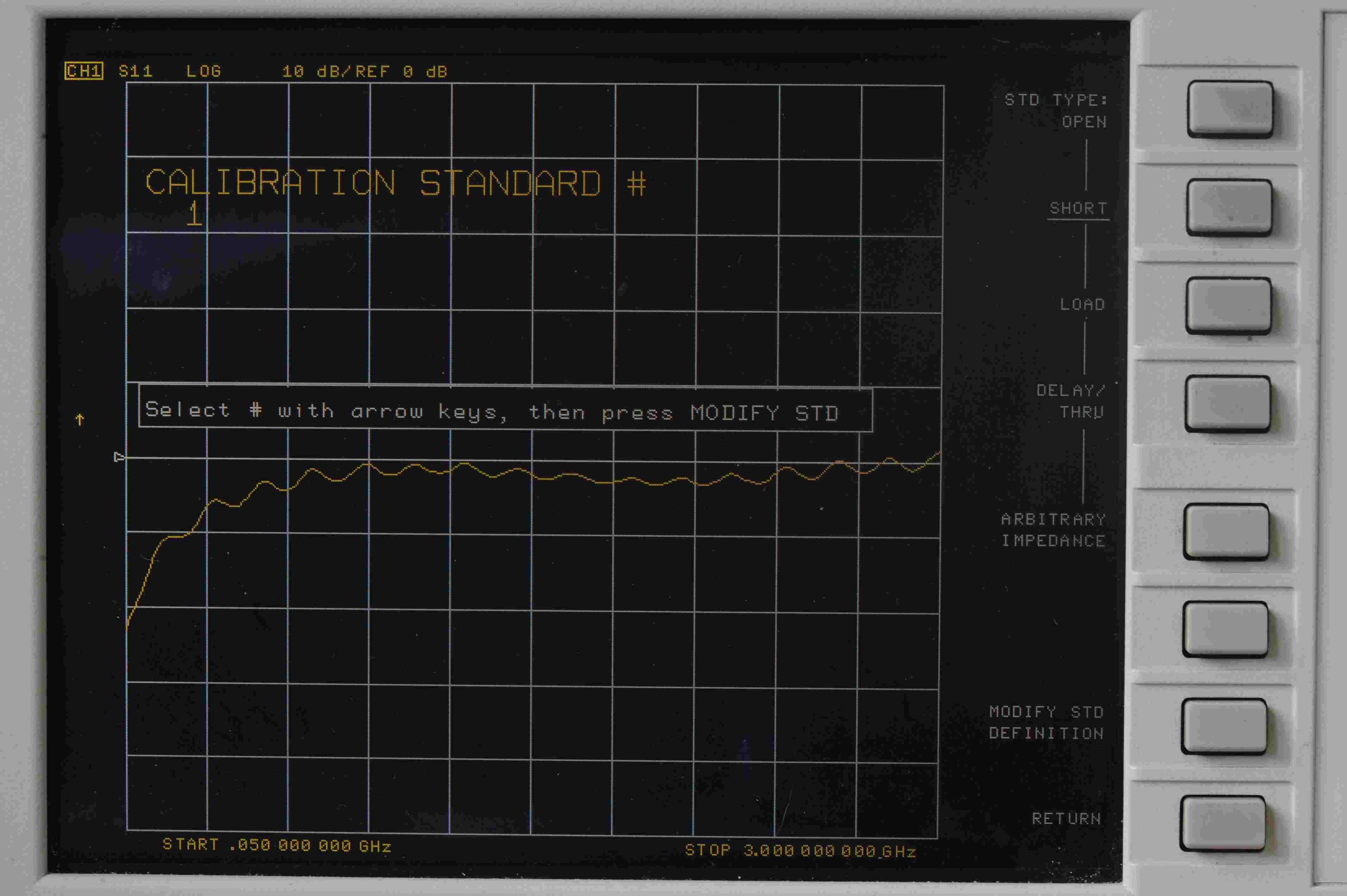
- Use the rotary control, or up/down arrows to select standard #2.
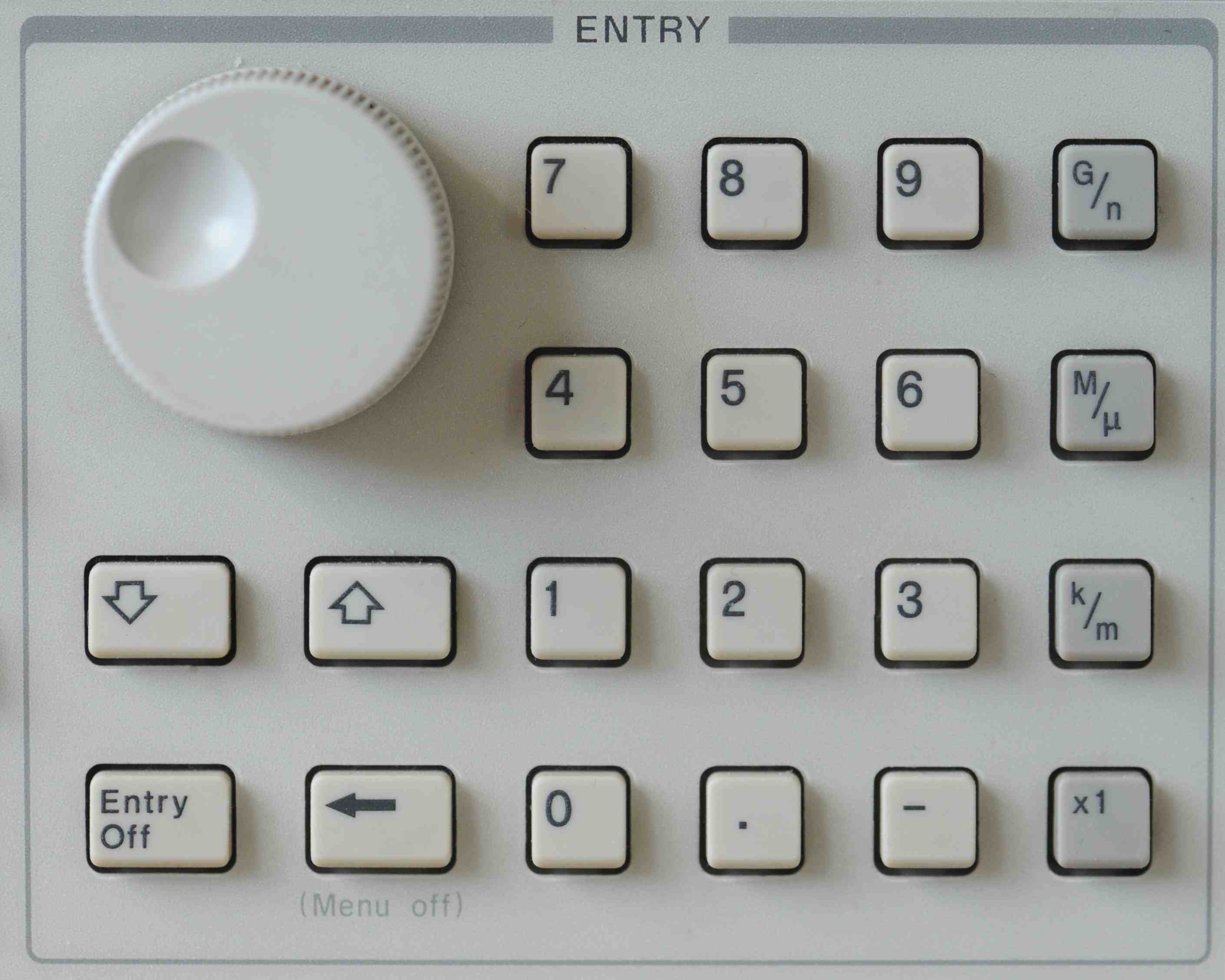
The rotary control can tend to be a bit fast, and change from different standards faster than you want. There's a bit more control with the up/down arrow keys, but
it does not matter what you use.
Rotate the rotary control clockwise slightly, or press the UP button once, to advance to standard #2. You should then see a screen like this, where note that the calibration standard is now #2, and the OPEN is underlined.
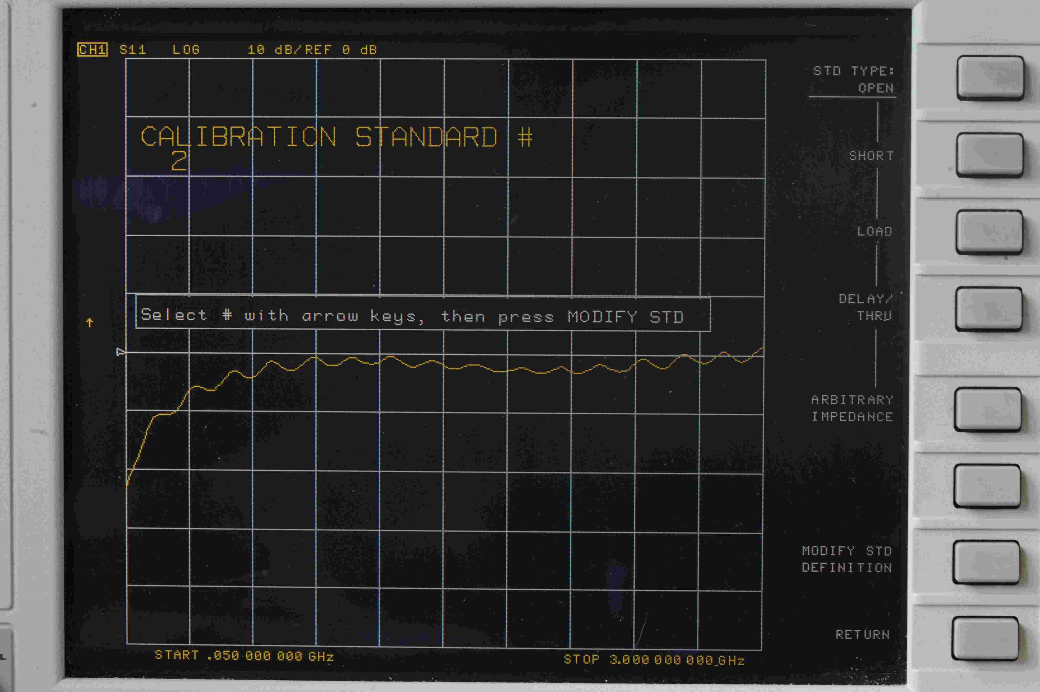
- Press MODIFY STD DEFINITION
and you will see you can modify the fringing capacitance coefficients C0, C1, C2 and C3.
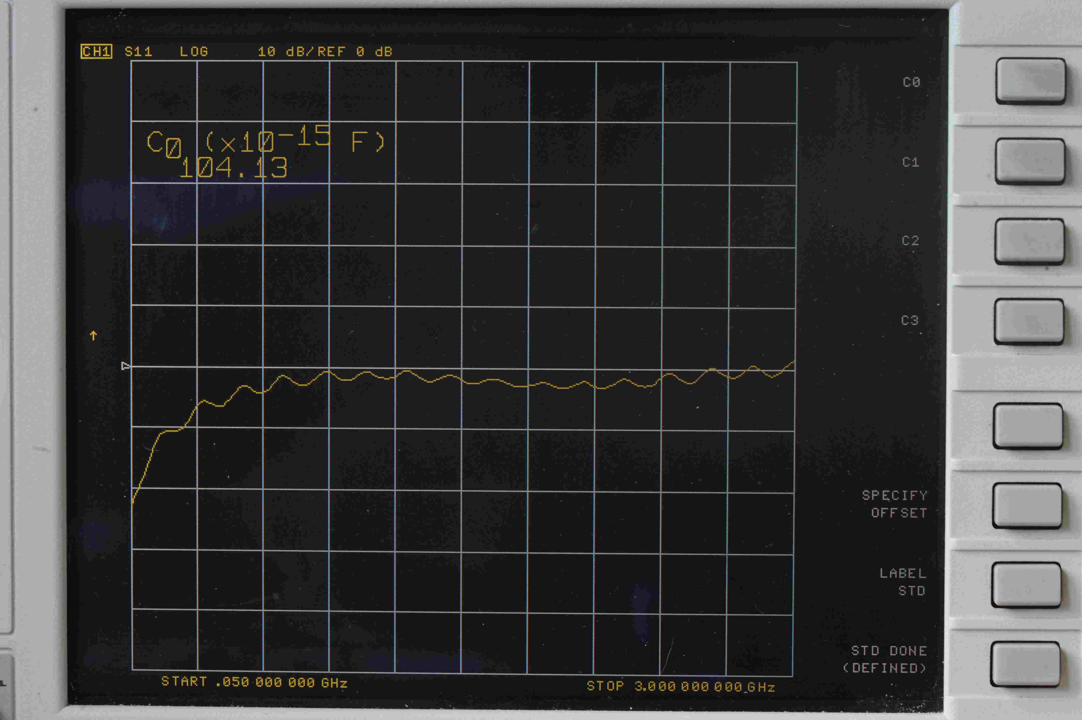
- Press C0
and observe some numeric value. In this case C0 is seen to be 104.13.
This is the value of C0 for the HP/Agilent/Keysight 85054B and 85054D calibration kits.
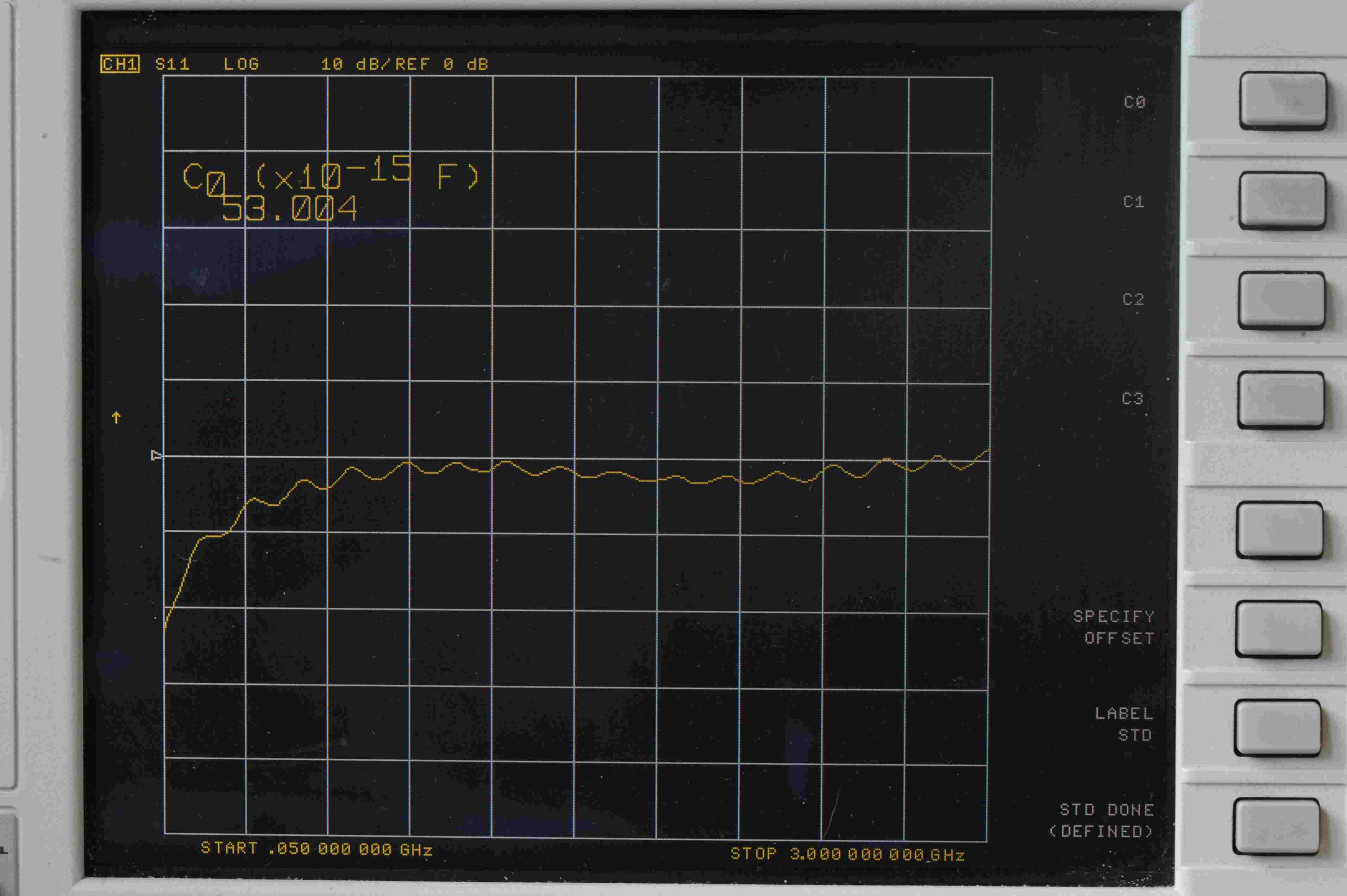
Next, in this tutorial we will modify C0 to be 53.004.
- Press 53.004, followed by x1
on the numeric keypad. You should see the value of C0 change from 104.13 to 53.004.
The other coefficients of the capacitance polynomial, C1, C2 and C3 can be displayed and changed just as C0 was modified. Next we will specify the offset parameters. These same parameters are used on the load, thru and short too.
- Press STD DONE (MODIFIED)
as we are finished modifying C0. Next we will modify some of the offset parameters.
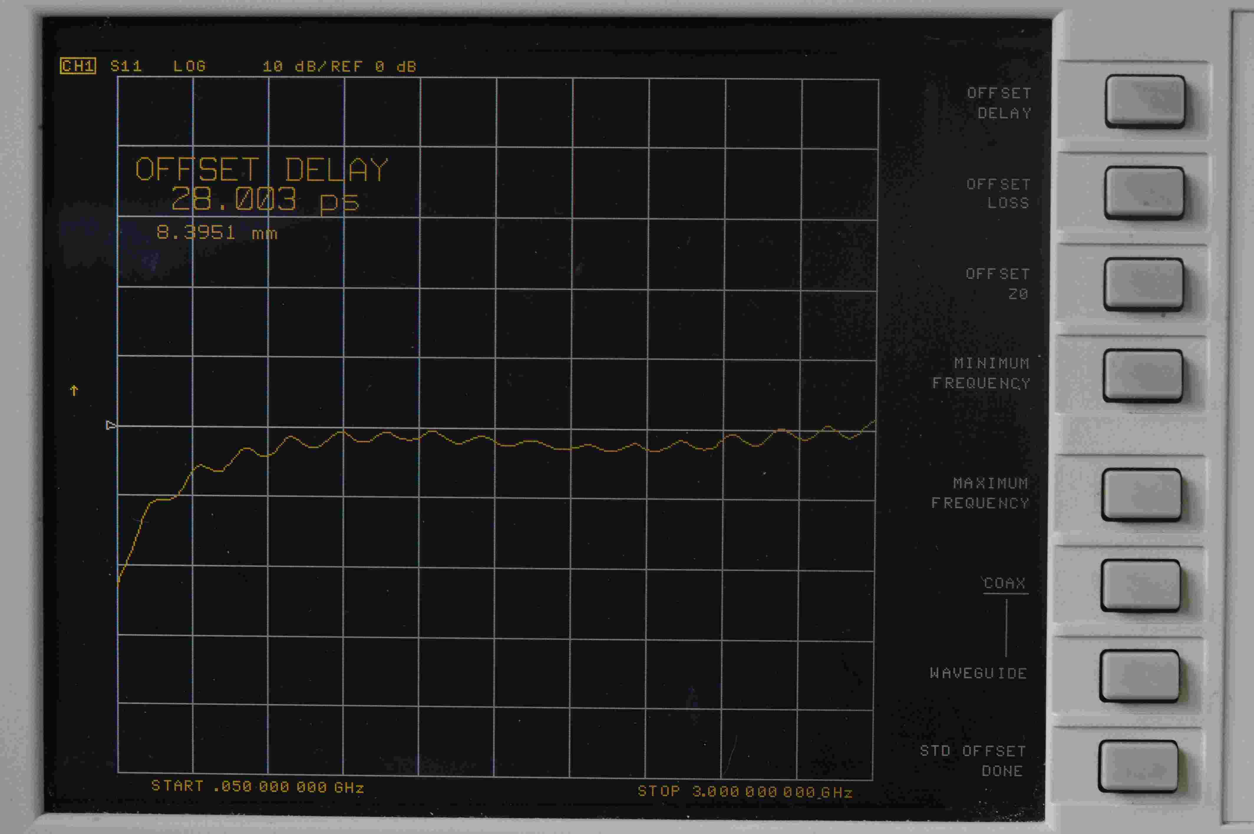
- Press SPECIFY OFFSET
after which you should see a further set of parameter that can be modified, including:
- OFFSET DELAY - the units are seconds, not ps as you might expect.
- OFFSET LOSS - units are Ω/s.
- OFFSET Z0 - the units are Ω.
- MINIMUM FREQUENCY - the units are Hz, not MHz or GHz as you might expect.
- MAXIMUM FREQUENCY - the units are again Hz.
- Whether the standard is COAXIAL or WAVEGUIDE.
If you then press one of the items on the manu, such as OFFSET DELAY, you will see the current value of offset delay, which for this example is 28.003 ps.
As with C0, C1, C2 and C3, the value can be changed by inputting a value on the numeric keypad. Note the units are seconds and not ps, as one might like. So
to enter an offset delay of 41.3 ps, there are two ways to do this.
- Enter the 41.3 ps in s, by inputting 0.0000000000413 on the numecic keypad, then pressing the x1 key.
- Enter the 41.3 ps in ns, by inputting 0.0413 on the numecic keypad, the pressing the G/n key at the top right of the instrument.
We find it preferable to input the offset delay in ns. All other offset parameters need to be set. The
default values for maximum frequency are 999 GHz, but we suggest you change that to the maximum frequency
of the kit you have purchased. For a 7 GHz SMA kit, one would enter 7, followed by the G/n key, which
would set the upper frequency to 7 GHz.
- Press STD OFFSET DONE
since we are finished modifying the offset parameters of that standard.
- Press STD DONE (MODIFIED)
since we have finished modifying all the parameters of that standard.
- Press LABEL KIT
in order that the kit can have a new name. We suggest the following names, to be consistent with
Kirkby Microwave.
- SMA for an SMA kit, when used with test port cables that have one male connector and one female connector that connect to the DUT. (The means the DUT will have one female and one male connector, which is typically the case with an attenuator.) Since such cables can be joined together
with no delay, the delay defined for the thru standard (#4), should be 0.
- SMA_F_F for an SMA kit, when used with two cables, both of which have male connectors on
the ends that connect to the DUT. In this
case, the female-female thru will needed during the transmission stage of the calibration, to
join the two male connectors. The delay of the female-female thru needs to be taken into account when
performing 2-port calibrations. This value would be typically 41 ps, which should be set in the
thru standard. (standard #4). The actual value will be given to you with each calibration kit,
on the USB stick.
- SMA_M_M for an SMA kit, in which both test port cables have female connectors, so a male-male
thru is needed to join them together. This is a pretty unlikely case, but would be needed if the DUT had two male connectors. We can't think of any DUT like that. The typical delay of the male-male thru
supplied in SMA kits is 71 ps
For an Type N calibration kit, use filenames having the same meaning as the SMA kit, i.e.
where the delay of the thrus would by typically 80 ps (female-female thru) and 130 ps (male-male thru).
Kirkby Microwave Ltd is registered in England and Wales, company number 08914892.
Registered office: Stokes Hall Lodge, Burnham Rd, Althorne, Essex, CM3 6DT.