![]()
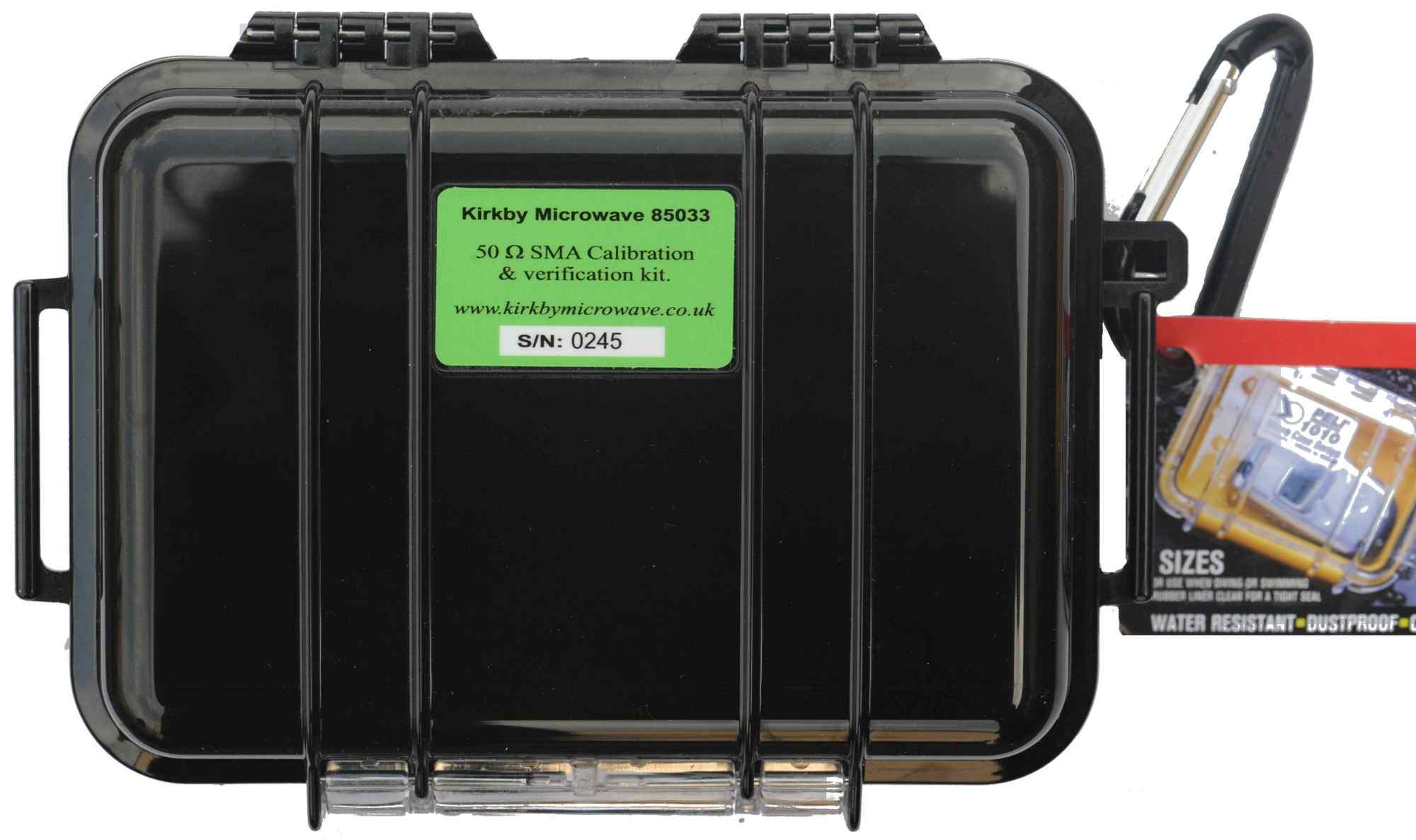
This page describes the 85033 SMA calibration kit, which may be used for the calibration of SMA, 3.5 mm or 2.92 mm devices. Other pages on our site show how to set up calibration kits for various VNAs. You will need to read this page about the SMA calibration kit, and a page that describes how to configure your particular model(s) of VNA.
The kit is particularly popular with
The kit is available with upper frequency limits of 7, 8, 9, 10, 11, 12 or 20 GHz. The loads will have a return loss of at least 32 dB to 7 GHz, and the phase of the calibration standards will follow the mathematical model within the accuracy given in the specifications. We can also give calibration data at user requested frequencies - e.g. 10.368 GHz is commonly requested. Please contact us about this for the price and availability.
VNAs manufactured by the following companies are fully supported.
We may be able to support other makes, such as Advantest, but we would need to be made aware of the model number first, to allow us to research this.
It is necessary to load the coefficients of the kit into the VNA. In some instances this will need to be done from the front panel, but for the following VNAs we can supply files which make uploading very easy
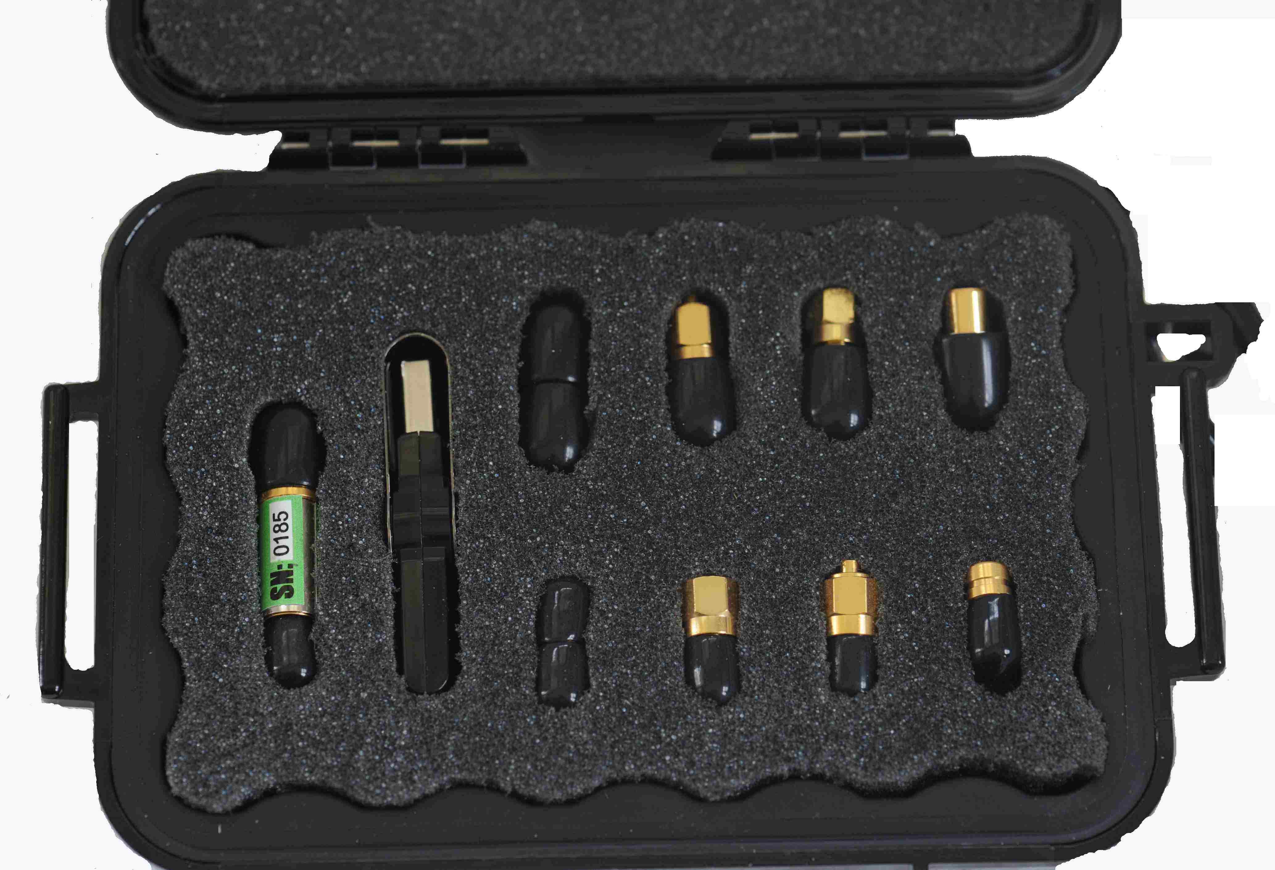
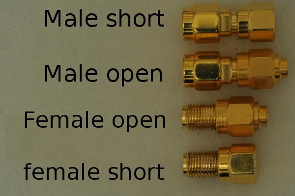
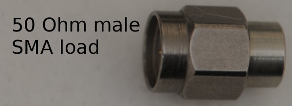
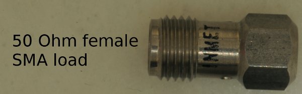
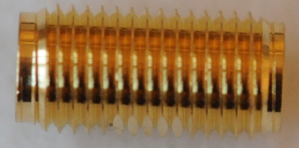
The 6 most important parts are the two opens, two shorts, and two load standards. (Rohde & Schwarz refer to the load as the 'match' standard, but we will use the term 'load' as it is more commonly used.)
To allow devices to be connected which don't have the appropriate sex of connectors for the device under test, then we include two adapters. One is a male-male thru and the other a female-female thru. (Although it is not obvious from the photograph, the female-female thru has flats on it, which allow it to be held with a 5.5 mm spanner.
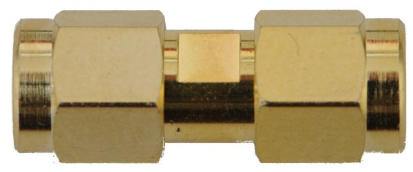
If your VNA supports unknown thru (Agilent Keysight term) or UOSM (Rohde and Schwarz term), then you will not need to worry about the delay of these adapters, but if the VNA does not support these method of calibration, then you need to consider the delay (ps) or electrical length (mm) of the adapters, which will be supplied.
For verification purposes, there's also an attenuator with measured S-parameters, which can help verify the system is set up correctly later.
![]()
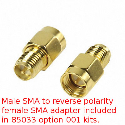
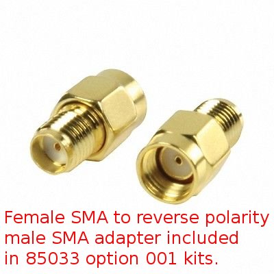
The kits can be provided with optional extras, such as reverse SMA adapters (option 001), U.FL adapters (option 002) or a torque wrench (option 004). A picture of the torque wrench is shown
This provides a fixed torque of approximately 4 lb inch, which is ideal for all SMA connectors.
The kit can also be supplied with a set of two reverse SMA adapters, which allow one to connect a standard SMA connector to either a reverse male or reverse female SMA connector.
Since late 2017, each kit has been supplied with individual data for that kit, which is put on the USB stick. Kits sold prior to this have generic coefficients. If you are unsure of the coefficients of your kit, please provide us the serial number of the kit. Coefficients are supplied in two forms
1. Human readable text files.
Using one of these files, it is possible to configure almost any VNA to work with our calibration kits.
Anritsu-coefficients.txt
Copper-Mountain-coefficients.txt
HP-Agilent-Keysight-coefficients.txt
L_A_Techniques-coefficients.txt
PicoVNA-coefficients.txt
Rohde-and-Schwarz-coefficients.txt
Tektronix-coefficients.txt
2. Files that can be read by specific models of VNAs.
We provide files readable by some Anritsu, Agilent and Keysight VNAs with every kit, as we can generate these automatically, without any human intervention, in about 1 second. These include
For other instruments, like those from Copper Mountain, Rohde & Schwarz, HP/Agilent, Pico Technology etc, we will generate files readable by a VNA when a customer requests them.
Despite more of our customers own HP 8753s than any other VNA, we have no completely automated way of generating files for the 8753s. We need to use some software Agilent wrote, or an actual 8753ES, since the file is a binary file in a proprietary binary format.
The following shows some pages we have on configuring specific VNAs. With the majority of customers owning instruments from Anritsu, HP/Agilent/Keysight, Rohde & Schwarz as well as Copper Mountain, we have more experience with them. But we do have customers with some of the rarer VNAs.
Anritsu
Copper Mountain (1-port and transmission/reflection)
Copper Mountain (Full 2-port & 4-port)
HP 8714
HP/Agilent 8753
HP/Agilent 8719, 8720 & 8722
HP/Agilent 8510
Agilent/Keysight PNA
Agilent/Keysight PNA-X
Agilent/Keysight FieldFox
Agilent/Keysight ENA
LA Techniques
Rohde & Schwarz
Using the correct torque on SMA connectors is particularly important, as hand tight is too loose, and yet it is easy to over-tighten with a spanner, which will either cause immediate failure, or reduce the lifetime. (For N-connectors, the use of torque wrench is not critical, as hand tight is really good enough.) The use of a torque wrench on SMA improves measurement repeatability, especially at the higher frequencies.
The torque wrench should only be used to tighten the SMA connectors - never to loosen them. For loosening the connector, an 8 mm spanner should be used.
For this, you will need to read the manual on your particular VNA. If you have problems, and the product is still supported by the manufacturer, they should be able to help. If it is an obsolete instrument, like an HP/Agilent 8753, 8719, 8720 or 8722, Kirkby Microwave might be able to help, but we do not have one of each type of VNA ever made!
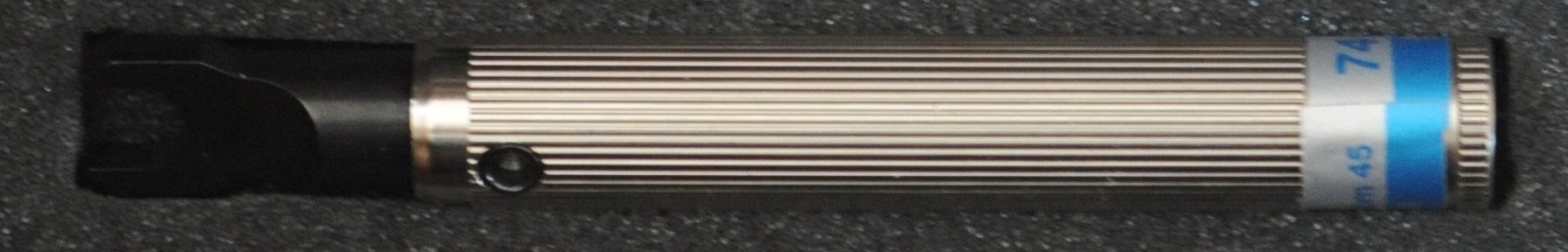
Once the VNA is set up to use the 85033 SMA calibration and verification kit, it is tempting to start making measurements. However, it is wise to verify that that the kit is correctly configured, and the VNA giving sensible results. Our kits include an attenuator
![]()
which has been measured using an Agilent 85052B calibration kit. The results of the measurements are stored on a USB stick included with the kit. We have a page about verification in our FAQ.
The kit included the following two additional components:
A calibration should be performed using just the SMA components - not any reverse polarity adapters. Once the calibration is performed, one or more adapters may be added, to allow the device under test (DUT) to be connected. Depending on what one wishes to measure, it may or may not be necessary to configure the VNA to use the adapters.
Kirkby Microwave Ltd is registered in England and Wales, company number 08914892. Registered office: Stokes Hall Lodge, Burnham Rd, Althorne, Essex, CM3 6DT.